| |
Rogers CLTE-MW DK2.94-3.02 Df0.0015 (0.003-0.010") Ceramic Filled PTFE Laminate
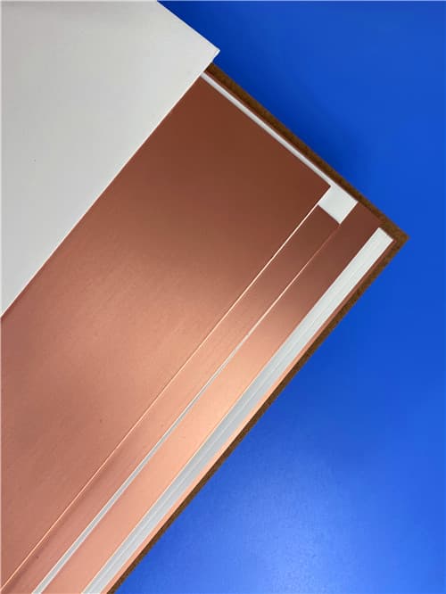
Brief Introduction
CLTE-MW laminates are ceramic-filled, woven glass reinforced PTFE composites developed to provide a cost-effective, high-performance material for circuit designers. This unique laminate system is well-suited for applications with thickness limitations due to either physical or electrical constraints. The seven available thickness options from 0.003" to 0.010" ensure ideal signal to ground spacing exists for today's 5G and other millimeter-wave designs. The laminates are reinforced with spread glass, which along with high filler loading helps minimize high-frequency glass weave effects on electromagnetic wave propagation.
Technical Features & Benefits
- Available in ultra-thin thicknesses: 0.003" to 0.010" (seven options)
- Ceramic-filled PTFE with spread glass reinforcement
- Dielectric Constant range: 2.94 to 3.02 ±0.04 (process), 3.03 to 3.10 (design)
- Low dissipation factor: 0.0015 @ 10 GHz
- Low z-axis CTE: 30 ppm/°C for excellent plated through hole reliability
- Low moisture absorption: 0.03%
- High thermal conductivity: 0.42 W/(m·K)
- High dielectric strength: 630 V/mil
- UL 94 V-0 flammability rating
- Excellent dimensional stability
- Low outgassing (NASA compliant)

Typical Properties: Rogers CLTE-MW
| Property |
Typical Value¹ |
Units |
Test Conditions |
Test Method |
| Electrical Properties | | | | |
| Dielectric Constant (process) | 2.94 to 3.02 ± 0.04 | - | 23°C @ 50% RH, 10 GHz | IPC TM-650 2.5.5.5 |
| Dielectric Constant (design) | 3.03 to 3.10 | - | C-24/23/50, 8-40 GHz | Microstrip Differential Phase Length |
| Dissipation Factor | 0.0015 | - | 23°C @ 50% RH, 10 GHz | IPC TM-650 2.5.5.5 |
| Thermal Coefficient of Dk | -35 | ppm/°C | 0 to 100°C, 10 GHz | IPC TM-650 2.5.5.5 |
| Volume Resistivity | 1.3 x 10⁷ | MΩ·cm | C96/35/90 | IPC TM-650 2.5.17.1 |
| Surface Resistivity | 2.5 x 10⁶ | MΩ | C96/35/90 | IPC TM-650 2.5.17.1 |
| Electrical Strength | 630 | V/mil | - | IPC TM-650 2.5.6.2 |
| Dielectric Breakdown | 44 | kV | D-48/50 | IPC TM-650 2.5.6 |
| Comparative Tracking Index | 600V / PLC 0 | class/volts | C-40/23/50 | UL-746A, ASTM D6054 |
| Thermal Properties | | | | |
| Decomposition Temperature (Td) | 500 | °C | 2hrs @ 105°C, 5% Weight Loss | IPC TM-650 2.3.40 |
| Coefficient of Thermal Expansion - x | 8 | ppm/°C | -55°C to 288°C | IPC TM-650 2.4.41 |
| Coefficient of Thermal Expansion - y | 8 | ppm/°C | -55°C to 288°C | IPC TM-650 2.4.41 |
| Coefficient of Thermal Expansion - z | 30 | ppm/°C | -55°C to 288°C | IPC TM-650 2.4.24 |
| Thermal Conductivity | 0.42 | W/(m·K) | Z Direction | ASTM D5470 |
| Time to Delamination | >60 | minutes | as-received, 288°C | IPC TM-650 2.4.24.1 |
| Mechanical Properties | | | | |
| Copper Peel Strength | 1.1 (6.0) | N/mm (lbs/in) | 10s @ 288°C, 35 μm foil | IPC TM-650 2.4.8 |
| Flexural Strength (MD, CMD) | 113, 99 (16.4, 14.4) | MPa (ksi) | 25°C ± 3°C | ASTM D790 |
| Tensile Strength (MD, CMD) | 83, 80 (12.0, 11.6) | MPa (ksi) | 23°C @ 50% RH | ASTM D3039/D3039-14 |
| Flex Modulus (MD, CMD) | 6468, 6360 (938.1, 922.4) | MPa (ksi) | 25°C ± 3°C | IPC TM-650 2.4.4 |
| Dimensional Stability (MD, CMD) | 0.22, 0.22 | mil/inch | after etch + bake | IPC-TM-650 2.4.39a |
| Physical Properties | | | | |
| Flammability | V-0 | - | - | UL 94 |
| Moisture Absorption | 0.03 | % | E1/105 + D48/50 | IPC TM-650 2.6.2.1 |
| Density | 2.1 | g/cm³ | C24/23/50 | ASTM D792 |
| Specific Heat Capacity | 0.93 | J/g·°K | 2 hours at 105°C | ASTM E2716 |
| NASA Outgassing | | | | |
| Total Mass Lost | 0.03 | % | TML/CVCM | ASTM E595 |
| Collected Volatiles | <0.01 | % | | ASTM E595 |
CLTE-MW Dielectric Constant by Thickness:
| Grade |
Panel Thickness |
Process Dk (10 GHz) |
Design Dk |
| CLTE-MW | 0.003" (0.076 mm) | 2.94 | 3.10 |
| 0.004" (0.102 mm) | 2.97 | 3.08 |
| 0.005" (0.127 mm) | 2.96 | 3.07 |
| 0.006" (0.152 mm) | 3.02 | 3.07 |
| 0.007" (0.178 mm) | 3.00 | 3.06 |
| 0.008" (0.203 mm) | 3.01 | 3.05 |
| 0.010" (0.254 mm) | 3.00 | 3.03 |
Application Areas
- Amplifiers
- Antennas
- Baluns
- Couplers and Filters
- 5G infrastructure
- Millimeter-wave applications
- Commercial and Consumer electronics
- Defense and Aerospace systems
Available Configurations
- Standard Thicknesses:
- 0.003" (0.076 mm) ± 0.0005"
- 0.004" (0.102 mm) ± 0.0005"
- 0.005" (0.127 mm) ± 0.0007"
- 0.006" (0.152 mm) ± 0.0007"
- 0.007" (0.178 mm) ± 0.0010"
- 0.008" (0.203 mm) ± 0.0010"
- 0.010" (0.254 mm) ± 0.0010"
- Standard Panel Sizes:
- 12" x 18" (305 x 457 mm)
- 24" x 18" (610 x 457 mm)
- Standard Claddings:
- Reverse Treated Electrodeposited Copper Foil:
- ½ oz. (18µm)
- 1 oz. (35µm)
- 2 oz. (70 µm)
- Very Low Profile Electrodeposited Copper Foil:
- ¼ oz. (9µm)
- ½ oz. (18µm)
- 1 oz. (35µm)
- Additional claddings, thicknesses, panel sizes, and metal plate options (including resistive foil) available upon request.
|
|


.jpg)
