| |
Rogers DiClad 527 2-Layer 0.6mm Immersion Gold PCB – Radar & Phased Array Systems
1. Introduction to Rogers DiClad 527 PCB
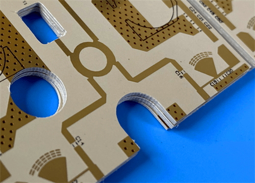
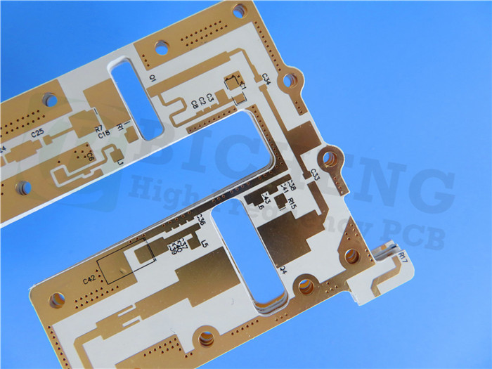
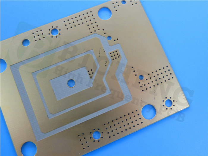
Rogers DiClad 527 laminates are woven fiberglass reinforced, PTFE-based composite materials for use as printed circuit board substrates. They offer a higher ratio of fiberglass reinforcement to PTFE content. This carefully controlled ratio provides a higher dielectric constant (Dk) range and better dimensional stability and registration. This 2-layer rigid PCB is constructed entirely with DiClad 527 as the core material, making it ideal for demanding microwave, radar, and phased array applications.
DiClad 527 laminates exhibit extremely low loss tangent, consistent mechanical performance, and stable electrical properties over a wide frequency range — critical for high-frequency, high-reliability applications. The material shows negligible performance drift caused by high humidity environments and excellent chemical resistance, making it suitable for both indoor and outdoor harsh environments.
2. Key Features of Rogers DiClad 527 PCB
Dk range of 2.4 to 2.6 at 10 GHz and 1 MHz, 50% RH Dissipation factor of 0.0017 at 10 GHz, 0.0010 at 1MHz, 50% RH TcDK of -153 ppm/°C ranging -10~140°C, 10 GHz Low Moisture Absorption: 0.03% CTE in X-axis: 14 ppm/°C, Y-axis: 21 ppm/°C, Z-axis: 173 ppm/°C Excellent dimensional stability and registration Stable Dk over wide frequency range Low circuit losses at high frequency Negligible performance drift caused by high humidity environments Excellent chemical resistance
3. Benefits of Rogers DiClad 527 PCB
Extremely Low Loss Tangent for high-frequency & high-power designs Excellent Dimensional Stability ensuring multi-layer registration accuracy Product Performance Uniformity and batch-to-batch consistency Electrical Properties Highly Uniform Across Frequency Consistent Mechanical Performance under thermal cycling Excellent Chemical Resistance for aggressive fabrication environments Stable Dk over wide frequency range ensures predictable impedance control Low circuit losses at high frequency enhance system efficiency Negligible performance drift caused by high humidity environments — ideal for outdoor and shipboard equipment
4. PCB Construction Details
| Item | Specification |
|---|
| Base material | Rogers DiClad 527 (woven fiberglass reinforced PTFE) |
| Layer count | 2-layer |
| Board dimensions | 49.63mm x 91.54mm = 1 PCS, +/- 0.15mm |
| Minimum Trace/Space | 4/6 mils |
| Minimum Hole Size | 0.3mm |
| Blind vias | No |
| Finished board thickness | 0.6mm (20 mil core) |
| Finished Cu weight | 1 oz (35 μm / 1.4 mils) outer layers |
| Via plating thickness | 20 μm |
| Surface finish | Immersion Gold |
| Top Silkscreen | Black |
| Bottom Silkscreen | No |
| Top Solder Mask | No |
| Bottom Solder Mask | No |
| 100% Electrical test | Used prior to shipment |
5. PCB Stackup (2-Layer Rigid Structure)
| Layer | Material | Thickness |
|---|
| Copper_layer_1 (Top) | Copper | 35 μm (1 oz) |
| Core | DiClad 527 | 0.508 mm (20 mil) |
| Copper_layer_2 (Bottom) | Copper | 35 μm (1 oz) |
6. PCB Statistics
| Parameter | Value |
|---|
| Components | 36 |
| Total Pads | 104 |
| Thru Hole Pads | 63 |
| Top SMT Pads | 41 |
| Bottom SMT Pads | 0 |
| Vias | 19 |
| Nets | 2 |
7. Rogers DiClad 527 Material – Product Introduction
Rogers DiClad 527 laminates are woven fiberglass reinforced, PTFE-based composite materials for use as printed circuit board substrates. They offer a higher ratio of fiberglass reinforcement to PTFE content. This carefully controlled ratio provides a higher dielectric constant (Dk) range and better dimensional stability and registration. The material is well known for extremely low loss tangent, consistent mechanical performance, and stable electrical properties over a wide frequency range — critical for high-frequency, high-reliability applications.
DiClad 527 exhibits negligible performance drift caused by high humidity environments and excellent chemical resistance, making it suitable for both indoor and outdoor harsh environments. The combination of low moisture absorption (0.03%) and stable Dk over temperature ensures reliable operation in aerospace, defense, and telecommunication infrastructure.
 DiClad 527.jpg)
8. Features and Benefits Summary
| Feature | Benefit |
|---|
| Low dissipation factor of 0.0017 @ 10 GHz | Enables low-loss, high-efficiency RF designs |
| Dk range of 2.4~2.6 @ 10 GHz & 1 MHz | Design flexibility for various impedance requirements |
| Low moisture absorption (0.03%) | Stable performance in humid environments, no drift |
| Excellent dimensional stability (low CTE X/Y) | Superior registration for fine-pitch designs |
| High glass-to-PTFE ratio | Better mechanical strength and processability |
| TcDK of -153 ppm/°C (-10~140°C) | Minimal Dk variation over temperature range |
| Woven glass reinforcement | Excellent handling and chemical resistance |
| No solder mask design | Minimizes signal loss at high frequencies |
9. DiClad 527 Typical Properties (Data Sheet)
| Property | Typical Value | Units | Test Condition | Method |
|---|
| Electrical Properties |
| Dielectric Constant (Dk) @ 10 GHz | 2.4 – 2.6 | — | 23°C / 50% RH | IPC TM-650 2.5.5.5 |
| Dissipation Factor (Df) @ 10 GHz | 0.0017 | — | 23°C / 50% RH | IPC TM-650 2.5.5.5 |
| Dissipation Factor (Df) @ 1 MHz | 0.0010 | — | 23°C / 50% RH | IPC TM-650 2.5.5.5 |
| TcDK (-10°C to 140°C) | -153 | ppm/°C | 10 GHz | IPC TM-650 2.5.5.5 |
| Volume Resistivity | 1.0 × 10⁷ | MΩ·cm | C96/35/90 | IPC TM-650 2.5.17.1 |
| Surface Resistivity | 1.5 × 10⁶ | MΩ | C96/35/90 | IPC TM-650 2.5.17.1 |
| Thermal Properties |
| CTE (X-axis) | 14 | ppm/°C | -55°C to 288°C | IPC TM-650 2.4.41 |
| CTE (Y-axis) | 21 | ppm/°C | -55°C to 288°C | IPC TM-650 2.4.41 |
| CTE (Z-axis) | 173 | ppm/°C | -55°C to 288°C | IPC TM-650 2.4.24 |
| Thermal Conductivity | 0.26 | W/(m·K) | Z-direction | ASTM D5470 |
| Mechanical & Physical Properties |
| Copper Peel Strength (1 oz) | 1.05 (6.0) | N/mm (lbs/in) | after solder float | IPC TM-650 2.4.8 |
| Moisture Absorption | 0.03 | % | E1/105+D48/50 | IPC TM-650 2.6.2.1 |
| Flammability Rating | V-0 | — | UL 94 | UL 94 |
| Density | 2.1 | g/cm³ | 23°C | ASTM D792 |
10. Primary Application Areas
Radar Feed Networks Commercial Phased Array Networks Low Loss Base Station Antennas Guidance Systems Digital Radio Antennas Filters, Couplers, LNAs Satellite communication systems Aerospace and defense electronics
11. Quality Assurance
Type of artwork supplied: Gerber RS-274-X Accepted standard: IPC-Class-2 Availability: Worldwide 100% Electrical test prior to shipment
12. Standard Thicknesses, Panel Sizes & Claddings
| Parameter | Options |
|---|
| Standard Core Thickness | 0.508 mm (20 mil) as used; other thicknesses available upon request |
| Standard Claddings | 1/2 oz (18 μm), 1 oz (35 μm), 2 oz (70 μm) copper foils (ED, reverse treated) |
| Panel Sizes | 12" x 18" (305 x 457 mm), 24" x 18" (610 x 457 mm) |
13. Dk Stability & Frequency Performance
DiClad 527 maintains a stable dielectric constant over a broad frequency range (1 MHz to 10 GHz) with minimal variation, ensuring predictable impedance control for high-frequency circuits. The typical Dk at 10 GHz is between 2.4 and 2.6, and the material shows exceptionally low sensitivity to humidity and temperature changes.
|
|
.jpg)
.jpg)
.jpg)
.jpg)