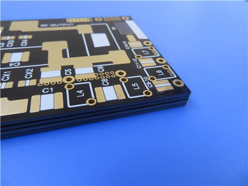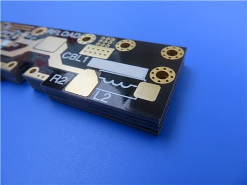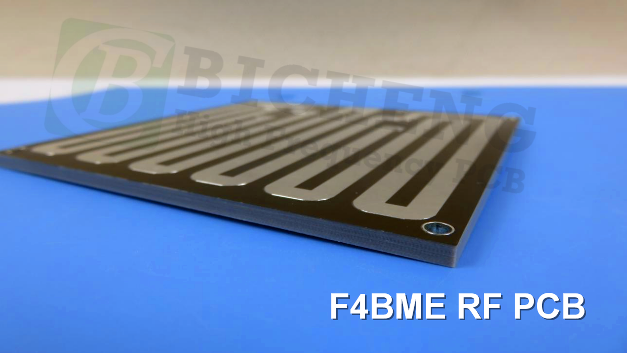
* PCBs are custom-made, picture & parameters for reference
F4BME High Frequency PCB Advanced Laminates for Microwave and RF Applications
(PCB's are custom-made products, the picture and parameters shown are just for reference)
Introduction
The F4BME High Frequency PCB series is constructed from a carefully formulated blend of fiberglass cloth, polytetrafluoroethylene (PTFE) resin, and PTFE film. This design enhances electrical performance compared to the F4B series, featuring a wider range of dielectric constants, lower dielectric loss, increased insulation resistance, and improved stability, making it a viable alternative to similar foreign products.
The F4BME and F4BM variants have the same dielectric layer but differ in copper foil combinations: F4BME uses reverse-treated foil (RTF) copper foil, providing excellent Passive Intermodulation (PIM) performance, precise line control, and reduced conductor loss. In contrast, F4BM utilizes ED copper foil for applications without PIM requirements.
By adjusting the ratio of PTFE to fiberglass cloth, both variants achieve precise control of the dielectric constant, ensuring low loss and enhanced dimensional stability.
Features & Benefits
Customizable dielectric constant (DK) options: 2.17 to 3.0
Low loss characteristics
F4BME with RTF copper foil for excellent PIM performance
Cost-effective and diverse size options
Radiation resistance and low outgassing
Commercially available with large-scale production
Laminate Models and Data Sheet
| Product Technical Parameters | Product Model & Data Sheet | |||||||||||
| Product Features | Test Conditions | Unit | F4BME217 | F4BME220 | F4BME233 | F4BME245 | F4BME255 | F4BME265 | F4BME275 | F4BME294 | F4BME300 | |
|---|---|---|---|---|---|---|---|---|---|---|---|---|
| Dielectric Constant (Typical) | 10GHz | / | 2.17 | 2.2 | 2.33 | 2.45 | 2.55 | 2.65 | 2.75 | 2.94 | 3.0 | |
| DK Tolerance | / | / | ±0.04 | ±0.04 | ±0.04 | ±0.05 | ±0.05 | ±0.05 | ±0.05 | ±0.06 | ±0.06 | |
| Loss Tangent | 10GHz | / | 0.001 | 0.001 | 0.0011 | 0.0012 | 0.0013 | 0.0013 | 0.0015 | 0.0016 | 0.0017 | |
| 20GHz | / | 0.0014 | 0.0014 | 0.0015 | 0.0017 | 0.0018 | 0.0019 | 0.0021 | 0.0023 | 0.0025 | ||
| Volume Resistivity | Standard | MΩ.cm | ≥6×10^6 | |||||||||
| Surface Resistivity | Standard | MΩ | ≥1×10^6 | |||||||||
| PIM (F4BME only) | / | dBc | ≤-159 | |||||||||
| Flammability | / | UL-94 | V-0 | |||||||||
Our PCB Capability (F4BME)
| PCB Capability (F4BME) | |||
|---|---|---|---|
| PCB Material: | PTFE glass fiber cloth copper clad laminates | ||
| Designation (F4BME) | F4BME | DK (10GHz) | DF (10 GHz) |
| F4BME217 | 2.17±0.04 | 0.0010 | |
| F4BME220 | 2.20±0.04 | 0.0010 | |
| F4BME233 | 2.33±0.04 | 0.0011 | |
| F4BME245 | 2.45±0.05 | 0.0012 | |
| F4BME255 | 2.55±0.05 | 0.0013 | |
| F4BME265 | 2.65±0.05 | 0.0013 | |
| F4BME275 | 2.75±0.05 | 0.0015 | |
| F4BME294 | 2.94±0.06 | 0.0016 | |
| F4BME300 | 3.00±0.06 | 0.0017 | |
| Layer count: | Single Sided, Double Sided, Multilayer, Hybrid | ||
| Copper weight: | 0.5oz, 1oz, 2oz | ||
| Dielectric thickness: | 0.127mm~12.0mm | ||
| PCB size: | ≤400mm X 500mm | ||
| Solder mask: | Green, Black, Blue, Yellow, Red etc. | ||
| Surface finish: | Bare copper, HASL, ENIG, Immersion Ag, Immersion Sn, OSP, ENEPIG | ||
A PCB and Typical Applications
Displayed on the screen is a 2-layer copper high-frequency PCB with a low DK of 2.2, utilizing F4BME material and HASL surface finish on a 3.0mm substrate.
F4BME high-frequency PCB finds applications in microwave, RF, and radar systems, as well as in phase shifters, passive components, power dividers, couplers, combiners, feed networks, phased array antennas, satellite communications, and base station antennas.
Final - F4BME series aluminum-based/copper-based boards
These F4BME series of laminates can provide aluminum-based or copper-based materials, where one side of the dielectric layer is covered with copper foil, and the other side is covered with either aluminum-based material or copper-based, serving as shielding or heat dissipation purposes.
Get a Quick Quote
Fill in the form below and our engineers will reply within 24 hours with technical specifications and pricing for F4BME High Frequency PCB Series (DK2.17-3.0 RTF Copper PIM).
.jpg)